HFlow: A Dynamic and Elastic Multi-Layered Data Forwarder
HFlow: A Dynamic and Elastic Multi-Layered I/O Forwarder
I. INTRODUCTION
Modern applications become more and more data-intensive as they explore, query, analyze, visualize, and process large amounts of data [1] in a short period of time. In traditional High-Performance Computing (HPC) architectures storage is treated as a global remote shared resource [2] typically exposed in a distributed software abstraction in the form of Parallel File Systems (PFS). Unlike traditional applications, where execution times are compute-bound, data-intensive applications [3], [4] often spend the majority of CPU cycles waiting for data, making them sensitive to the performance of the underlying storage systems - a phenomenon widely known as the I/O bottleneck problem [5]. To alleviate this bottleneck, a new architectural trend proposes the placement of fast intermediate storage resources [6] (e.g., NVMe SSDs, 3DXpoint, PCM) which aim to mask the I/O gap between compute nodes and the underlying PFS and has been shown to accelerate data-driven discovery [7].
The I/O bottleneck on PFS arises from various application behaviors: a) highly concurrent I/O [8] that can lead to interference, complex locking, and metadata contention, b) highly bursty I/O [9] that can lead to bandwidth saturation, increased CPU stall time, and resource idleness in between phases, c) highly iterative I/O [10] that can lead to expensive data movements, network pressure, and irregular data access patterns. Several software solutions have been proposed to mitigate the negative effects of such behaviors. These include I/O Forwarders [8], [11] (IOF), which reduce the client concurrency by aggregating several I/O requests; Burst Buffers [12], [13] (BB), which provide a fast temporary storage for absorbing I/O bursts and asynchronously moving data to PFS; and Data Staging [10], [14] (DS), which enables in-situ data analysis and visualization to reduce expensive data movement between storage and compute nodes. These I/O technologies mask the data management complexity by transparently performing these optimizations and improve applications' I/O performance [15], [16].
As the scale of modern systems grows, managing such complex multi-layered I/O infrastructure (i.e., IOF, BB, DS, PFS) and extracting optimal performance becomes challenging. This difficulty is further highlighted by the rise of multi-tenancy in HPC [17]. In this study, we make the following observations. First, each of the abovementioned software solutions was designed with different objectives and is typically managed and maintained in isolation [18]. This leads to unnecessarily bloated software stacks and uncoordinated interactions between these layers [7] and limits how applications can utilize these resources in a workflow. Second, applications access these intermediate I/O resources by static allocations or time-based reservation mechanisms [19]. However, applications distribute work across ranks non-uniformly [20], [21] which may lead to load imbalance and performance mismatching ultimately resulting in sub-optimal I/O performance. Third, to reduce resource contention, each intermediate I/O layer is exclusively provisioned to applications for their lifetime [22]. However, applications perform I/O in phases [23] which leads to increased resource idleness between compute and I/O resulting in a misutilization of these specialized hardware resources [13]. Finally, in-situ [24] and in-transit [25] operations can significantly reduce the data movement and time-to-insight and is a crucial functionality of modern data-intensive applications [26], [27]. Since most intermediate I/O layers gain data ownership for a given time, they are a natural ideal candidate to carry forward such operations (e.g., data deduplication, filtering, compression, etc.). However, existing intermediate I/O solutions lack support (or are limited at best) for complex in-situ and in-transit user-defined computations. These observations motivate a new generation of I/O forwarding software that transparently unifies these intermediate I/O layers and optimizes all data movements generated by modern data-intensive applications.
In this work, we present HFlow , a dynamic and elastic multilayered I/O forwarding technology, which addresses the identified challenges by utilizing a real-time continuous data movement paradigm. HFlow introduces an abstraction, called ByteFlow , which captures an application's data movement requirements and semantics (i.e., data aggregations, filtering, compression, ephemeral data stashing, etc.). A ByteFlow is defined by a pair of endpoints (i.e., source and sink) and a set of transmission rules (i.e., how the bytes should flow between the endpoints). On one hand, HFlow supports a variety of application and data representations by transforming forwarding requests between the endpoints into a data representation, the Data Parcel , that supports a publish-subscribe model. On the other hand, the set of transmission rules are defined through the chaining of user-defined tasks (compression, aggregation, filtering, data caching, etc.) in the form of a DAG. The data-centric and ephemeral nature of these tasks combined with resource utilization monitoring allows HFlow to dynamically and elastically adjust to the load of the system and I/O behavior of the applications. The high customization of the tasks further enhances HFlow 's capabilities to manage a variety of I/O resources by behaving in complex and diverse ways. The combination of all these features allows HFlow to improve the run-time of applications.
In summary, HFlow demonstrates the following contributions:
- How exposing all intermediate I/O resources under a single platform and a unified interface can reduce software bloating and improve interactions between layers.
- The effectiveness of run-time dynamic resource mapping to avoid load imbalance and adapt to applications changes in I/O behavior.
- The effectiveness of elastic resource management , where resources can automatically grow and shrink to handle the demands of all applications running in the system.
- How enabling complex user-defined in-situ/in-transit computations can help reduce the I/O load of the system.
II. BACKGROUND AND MOTIVATION
A. Intermediate I/O Resources (InterIOR)
Intermediate I/O Resources (InterIORs) are temporary storage areas physically deployed between compute nodes and storage nodes used by applications to bridge the gap between CPU performance and storage performance. There are three major types of InterIORs: I/O Forwarders, Burst Buffers, and Data Stagers. In this section, we will describe each of these technologies.
-
I/O Forwarders: The I/O Forwarding Layer (IOFL) is an InterIOR layer that intercepts I/O requests made by applications on compute nodes and forwards them to a PFS located on storage nodes. IOFs are commonly deployed in large-scale supercomputers [28][30]. The IOFL is designed to reduce the I/O request concurrency, coordinate reading/writing, enable buffering [19] and prefetching [31] for the PFS. These properties provide two main benefits: First, a reduction in the I/O contention caused by concurrent I/O accesses [11], and second, the removal of the filesystem clients on compute nodes, which typically contribute to OS noise [8]. However, despite these benefits, the IOFL also has a few disadvantages; for example, most supercomputers implement a fixed-mapping strategy between compute nodes and IOFs, which can lead to load imbalance and interapplication interference [21]. Some solutions have been proposed that map jobs to IOFs when the job is deployed [19]; however, these approaches require profiles of the application and cannot re-map jobs dynamically during runtime, which also leads to load imbalance.
-
Burst Buffers: The Burst Buffer Layer (BBL) is an InterIOR layer that buffers data for applications [32]. The BBL is designed to absorb I/O bursts, in contrast to the IOFL, which is designed to coordinate and reduce the I/O requests made to the PFS. BBs are deployed in large-scale supercomputers, including Cori [33] and Trinity [34]. BBs are comprised of node-local or shared storage devices such as NVRAM. The BBL accelerates several types of workloads, including checkpoint-restart, non-sequential table lookup, and out-of-core access [7]. However, shared BBs are subject to cross-application I/O interference when multiple applications are attempting to write to the same BB concurrently [12]. In addition, allocating dedicated BBs causes resource under-utilization and load imbalance due to the fact that many HPC applications spend small fraction of their runtime in I/O phases, where no I/O is happening [13]. Furthermore, for data-intensive workloads, the batch-based approach for draining data is typically used to manage BBs, resulting in significant I/O stall times due to BB capacity being exhausted, which requires applications to stall until the BB has been drained enough to accept further I/O request [9].
-
Data Staging: The Data Staging Layer (DSL) is an InterIOR layer that dedicates a portion of compute resources for storing data. The main difference between the DSL and the BBL is that DSL was designed to provide concurrent access to application data whereas the BBL was designed to absorb I/O bursts for individual applications. The DSL provides multiple benefits: fast, asynchronous data movement between compute nodes and the staging area using RDMA [10]; fast indexing, querying, and monitoring of simulation data in the staging area by multiple applications concurrently [14]; and in-situ data processing [27].
B. Data Streaming
To support the ever-increasing demand of processing streaming data, both Cloud computing and HPC communities have recently proposed and developed their own Data Stream Processing (DSP) systems. To the best of our knowledge, there are many DSP platforms which have emerged in the Cloud-based space in the last few decades, such as Apache Flink [35] [36], Google Cloud DataFlow [37] and Kafka Streams [38]. These systems have been used extensively in industry and scientific fields. Although these DSP systems may differ in their architecture, they are mainly designed and optimized for processing streaming data in order to get low latency and high throughput. However, compared with the DSP development in Cloud computing, DSP systems are neither well-supported nor widely used in HPC. Two main DSP systems exist in HPC: MPI Streams [39] [40], a library that extends Message Passing Interface (MPI) to provide streaming operations in HPC environments; and Pilot-Streaming [41], a framework that supports Cloud native streaming applications and their resource management requirements on HPC platforms. Although MPI Streams and Pilot-Streaming partially make up for a deficiency in supporting DSP on HPC platforms, the deficiency is still there. Further, a growing number of data-intensive applications are moving to the HPC platforms because of their high processing capabilities and larger memory capacities with the advent of exascale computing. Therefore, it is becoming very important and necessary to provide data stream processing on HPC platforms.
C. Motivation
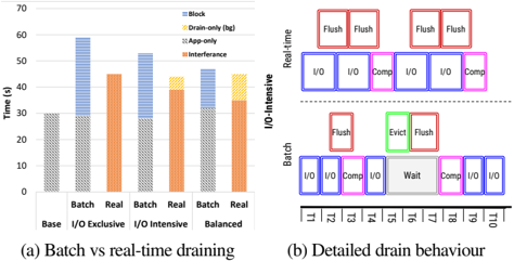 Fig. 1: Batch vs real-time draining
Three observations motivate us to create a new Data Forwarding System based on a real-time data movement engine: 1) batch-based approaches to data draining result in significant I/O stalls on dataintensive workloads, 2) software technologies that manage the InterIORsare independent, which increases the complexity of code for the user, and 3) fixed mappings are widely used for associating jobs to InterIORs, resulting in load imbalance and resource under-utilization.
- InterIORs often depend on batch-based approaches for data movement, which only drain data when some event is triggered, such as entering the computation phase of a checkpoint-restart application or capacity being depleted. In compute-intensive workloads (i.e. compute phases are dominant, assuming an application with a compute phase and an I/O phase, such as in a checkpoint-restart application), batch-based approaches can overlap the cost of draining with the phase of computation, assuming the capacity of the InterIOR does not get depleted during the I/O phase. However, on data-intensive workloads (i.e. workloads where draining is triggered during a single phase of I/O), this approach may result in significant slowdown due to I/O stalls caused by the need to wait for the space to become available before accepting more I/O requests. However, a pull-based streaming model to perform data movements continuously can amortize the cost of I/O operations to the intermediate layers and reduce the I/O stall time, increasing performance.
To demonstrate this, we conducted a study on the performance of different workloads using continuous and batch-based draining. We conducted tests for three workloads generated using IOR [42]:I/OExclusive, I/O-Intensive, and I/O-Balance. In Figure 1a, we see that the real-time drain scheduler outperforms the batch-based drain scheduler. We illustrate the workloads with Gantt charts in Figure 1b to showcase how the batch-based scheduler depleted the BB capacity, causing significant stall time (wait phase) for incoming I/O. Therefore, we conclude that, there is a large potential for a real-time drain scheduler to improve the performance of data-intensive workloads.
-
Although various InterIOR layers exist (IOFL, BBL, DSL), separate applications are used to manage them IOFL, BBL, and DSL [43]. This lack of unification makes interacting with the different layers more complex and system-dependent, increasing the programming burden for the user. A unified platform would reduce the programming overhead for the user by abstracting the various interfaces provided by the different InterIOR software technologies.
-
Fixed mappings are widely used to associate jobs with InterIORs, which leads to load imbalance and resource under-utilization in InterIORs. Thus, a system which is able to elastically manage the provisioning of InterIORs and dynamically map jobs to InterIORs can significantly reduce the effects of load imbalance on InterIORs.
III. HFLOW: NEXT-GEN I/O FORWARDING
A. Design Requirements
In this work, we present a novel protocol for I/O Forwarding technology, HFlow. HFlow features a real-time data movement paradigm that, in combination with the ByteFlow abstraction, enables HFlow to satisfy the challenges presented in section I:
- Unified Forwarding Platform: A new I/O forwarding system should expose all intermediate I/O resources under a single platform to provide a unified interface. [7].
- Dynamic resource mapping: A new I/O forwarding system should dynamically map jobs to InterIOrs to avoid load imbalance and inefficient resource utilization caused by changes in the I/O behavior of applications [19].
- Elastic resource management: A new I/O forwarding system should enable the automatic, real-time provisioning of InterIOrs, as providing the minimum amount of resources necessary to handle the demands of all applications running in the system at any moment in time avoids resource under-utilization [13].
- In-situ/in-transit operations: A new I/O forwarding system should empower users with the ability to enhance their I/O pipeline with an active forwarding model capable of data transformations [24].
B. HFlow Data Model
A ByteFlow is defined by a pair of endpoints (i.e.,source and sink), called ByteSockets , and a set of transmission rules (i.e., how the bytes should flow between the endpoints), called ByteFlow Schema .
The ByteFlow Schema defines the internal behaviour of the ByteFlow , and establishes the functionality and order (in the form of a DAG) of the tasks that need to be perform on the data flowing through the ByteFlow , more details and a sample of a ByteFlow Schema are provided in section III-D7.
The ByteSockets are of key importance to HFlow as they are the two I/O end-points of a ByteFlow that, in general, represent the client and the final storage system.
ByteSockets have five core components:
- Type : represents if the ByteSocket is a source (where HFlow takes data from) or a sink (where HFlow moves data to).
- Data Representation : defines how HFlow should internally interface with the ByteSocket . For example, representations can include queues, HDF5 files, POSIX files, Redis maps, or NoSQL tables.
- Access Information : defines how to access the ByteSocket . For example, It can be an IP and port or a mount point.
- Identifier : defines the location of data. For example, the path to a file or a key in a database.
- Flags : a collection of inputs which specify the management of a ByteSocket . For example, the priority of data, data deletion, write mode, etc.
C. High-Level Architecture
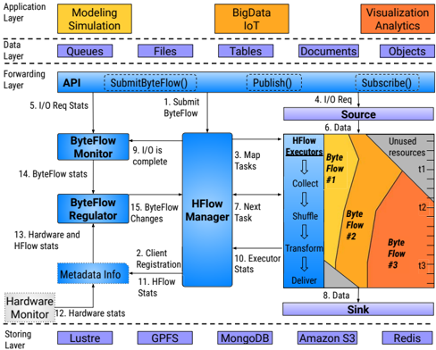 Fig. 2: HFlow Architecture
In Figure 2 we can see the overall path of a job on HFlow .On initialization of HFlow , the HFlow Manager is deployed on a single node. The HFlow Manager will spawn a default number of HFlow Executors . Users create a custom ByteFlow Schema defining the ByteSocket and any in-transit operations and then compile it into a shared library. At runtime, the applications will submit the ByteFlow Schema to the system (1) and the HFlow Manager will register it (2). On submission, the HFlow Manager will load the Schema dynamically from the shared library and map a default number of Collectors defined in the ByteFlow Schema to a subset of the HFlow Executors (3). At this point, the application is able to begin submitting I/O Requests.
When the application publishes a request into the source (4), the Collectors will pull the requests and convert them into Data Parcels (6). When finished, each task (including the Collectors ) asks the HFlow Manager for the location of the next task (7) and emits the Data Parcel . When the Delivery Tasks defined in the ByteFlow Schema get executed, the Data Parcels are persisted to the sinks (8).
Four statistics are collected periodically by HFlow . First, when an I/O request is submitted, the ByteFlow Monitor is given statistics of the request, such as request size (5). Second, the HFlowManager notifies the ByteFlow Monitor when an I/O request has been completed (9). Third, each HFlowExecutor individually collects statistics about the flow of Data Parcels in that HFlow Executor (10) and sends them to the HFlow Manager to be aggregated into software runtime statistics, which represent the flow of Data Parcels in the entire system (11). Finally, a Hardware Monitor maintains a view of the current status of the interIOR resources (12). These statistics are periodically sent to the ByteFlow Regulator (13,14). The ByteFlow Regulator uses these statistics to determine the optimal number of resources that should be allocated for each ByteFlow and sends these suggestions to the HFlow Manager (15), which is responsible for elastically reshaping the pool of HFlow Executors and dynamically modifying the mappings of tasks to HFlow Executors .
This elasticity model can also be seen on Figure 2. Where three ByteFlows are being used by three applications. (marked in grey are unused resources). Two applications ( Modelling and BigData ) are registered on start with a default set of resources. Up until time t 1 , the I/O demand of two applications continue to rise, requiring more resources to be provisioned and for the mappings to change dynamically, resulting in wider ByteFlows . At time t 2 , the Visualization application is launched and registered with HFlow . With the addition of this application, all available resources become provisioned. In this example, the I/O demand of the Visualizing application is higher than the other two combined, resulting in the ByteFlows of those two applications being stripped of resources. At time t 3 , the Modeling application finishes, and as the I/O demand of the Big Data application begins to decrease, resources start being deallocated elastically since they are being under-utilized.
D. HFlow Components
- HFlow API: Application interaction with the ByteFlows can be perform in one of two ways: through the native HFlow API or through a transparent mode where HFlow intercepts I/O calls.
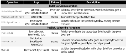 Fig. 3: Table of HFlow API Operations
The HFlow API can be seen in table 3. It consists of two components:
- ByteFlow Administration: provides users with the tools needed to design and manage ByteFlow Schemas .
- Publish/Subscribe Paradigm: defines the methods applications use to interact with HFlow during runtime.
-
HFlow Manager: The HFlow Manager is the brain of HFlow . It is responsible for receiving the ByteFlow Schema registration and instantiating the ByteFlow through the spawning of Collectors , elastically managing the HFlow Executor by spawning or killing them, parsing ByteFlow Regulator suggestions to dynamically map tasks to HFlow Executors , directing the task communication by informing each HFlow Executors of the destination of its Data Parcels , and, finally, aggregating the software runtime statistics provided by the HFlow Executors .
-
HFlow Executor: The HFlow Executor is the engine of HFlow . It runs as a single process with control of a number of threads. Its main responsibility is to spawn, control and terminate the execution of tasks and feed them the incoming DP . It is remotely spawned by the HFlow Manager . On receiving a request from the HFlow Manager , containing a WorkerID , a SchemaID , and a TaskID , the HFlow Executor will obtain a reference to the task to be executed. When the WorkerID is not defined, this task will be placed on the thread with the minimum load and will begin running with a new unique ID. If the WorkerID is defined, the task is given to the thread with that ID. Once a task is running, it will receive some Data Parcels . The processed Data Parcels are emitted to the HFlow Executors , which will contact the HFlow Manager , it will return an ExecutorID and WorkerID pair to which the Data Parcels will be sent. Finally, either under the request of the HFlow Manager or because no new Data Parcels are received for the task, tasks can be killed and their threads removed and dequeued. The combination of this behaviours is what allows HFlow to provide the dynamic and elastic behaviour.
- Metadata Info: Implemented utilizing an in-memory key-value object database. It is responsible for storing HFlow runtime statistics, and hardware resource usage.
- ByteFlow Monitor: The ByteFlow Monitor tracks the statistics of the ByteFlow . Whenever an API call is made, it immediately sends statistics to the ByteFlow Monitor , which can then be accessed as necessary by the ByteFlow Regulator in order to determine resource allocation. Since ByteFlow Monitor is designed to balance HFlow resource usage, the major statistics tracked by the ByteFlow Monitor are the InFlow (i.e. rate of data input) and OutFlow (i.e. rate of data output). This information is pushed out to the ByteFlow Regulator at fixed intervals either of time, data, or operation count.
- ByteFlow Regulator: The ByteFlow Regulator is the core control center of the dynamic and elastic model behind HFlow . At its core, the function of the ByteFlow Regulator is to generate a set of suggestions instructing the HFlow Manager to reshape the resources allocated to any given ByteFlow . The ByteFlow Regulator requires the InFlow and OutFlow , software-level statistics, and hardware resource statistics. With this information, it will generate the suggestions. Algorithm 1 showcases a simplified version where
Algorithm 1: ByteFlow Regulator Algorithm 1 CalculateRate (jobs) 2 foreach job ∈ jobs do 3 InFlow = InFlowMap[job] 4 OutFlow = OutFlowMap[job] 5 variation = | OutFlow -InFlow | 6 if InFlow = 0 ∨ OutFlow = 0 then 7 continue 8 if variation ≥ conf.UpdateVariation then 9 AlterNodes(job, OutFlow, InFlow) 10 return 11 AlterNodes (job, OutFlow, InFlow) 12 if OutFlow ≥ InFlow then 13 multiplier = AlterType::SHRINK 14 else 15 multiplier = AlterType::GROW 16 variation = | OutFlow -InFlow | 17 difference = variation - (conf.UpdateV ariation/2) 18 nodeVar = difference*multiplier/conf.UpdateStep 19 ResourceAllocation resources(job, nodeV ar ,0, 0) 20 HFlowManager.ChangeResourceAllocation(resources) 21 return1 struct SimpleSchema : public Schema { 2 SimpleSchema(uint32 t job id): Schema(job id) {} 3 void CreateDAG() override { 4 collector = new HFLowCollector(); 5 delivery = new HFLowDeliver(); 6 collector-> links.push back(sink); 7 } 8 } ; 9 typedef struct HFlowCollector : public Collector { 10 HFlowCollector() : Collector(), server id(0) {} 11 Parcel Run() override { 12 client = new Client(job id ); 13 while(wait for(microseconds(100))) { 14 parcels = client-> Pull(server id); 15 if(parcels.size() == 0) continue; 16 for(parcel: parcels) { 17 data = client-> GetData(parcel); 18 client-> DeleteData(parcel); 19 client-> UpdateStatus(parcel); 20 emit(job id , id , parcel, data);Listing 1: Simple ByteFlow Schema and a collector
only InFlow and OutFlow are considered. The algorithm triggers a re-scaling if the difference between InFlow and OutFlow exceeds a given threshold. A re-scaling involves reshaping the resources of the given ByteFlow by an amount proportional to the UpdateStep , which defines the maximum amount of flow that a single processing unit (e.g. a core or a node) is capable of handling.
- ByteFlow Schema:
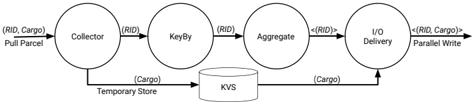 Fig. 4: A visualization of a ByteFlow for data writing
The ByteFlow Schema is a DAG that orders and establishes the functionality of a series of independent tasks that need to be performed on the data flowing through the ByteFlow . The order and functionality of the tasks are user-defined and provide the user with the flexibility to manage their own data. In addition, this flexibility allows HFlow to interact with a variety of sources and sinks as the Data Collectors and Data Deliverers can be customized to interact with the desired target. Some limitations do exist: a) HFlow tasks have to be state-less as we assume that tasks can be killed and spawn at any point in time; b) HFlow does not currently support interaction between two ByteFlows . As an example, Listing 1 showcases a simple and generic ByteFlow Schema . Figure 4 visualizes a Byteflow defined by a more complex ByteFlow Schema that defines an aggregation task to achieve higher performance over HDD while interacting with a temporary KVS to store the in-transit data to reduce network usage.
E. Design Implications
In this section, we detail how the design of HFlow impacts the performance and management of the storage system.
-
Amortizing Flushing cost: Data-intensive applications can exhaust the capacity of InterIORs when a batch-based drainage approach is used for data movement, resulting in significant I/O stalls that reduce application performance. The real-time drain approach that HFlow employs is able to reduce this penalty by draining data before the capacity is expended. However, this approach can cause I/O interference due to the fact that InterIORs are receiving and sending data at the same time. When applications are more compute-bound, the real-time draining approach can result in performance degradation due to this interference. Therefore, HFlow is best suited for data-intensive workloads.
-
Mitigating uncoordinated I/O: When multiple applications attempt to perform I/O with a backend storage service such as PFS without coordination, cross-application I/O interference is incurred. Previous research has been conducted on coordinating this I/O for particular InterIOR layers, such as the IOFL, BBL, and DSL. However, these technologies work in isolation and still interfere with each other. HFlow is able to manage the diverse set of InterIOR software and hardware technologies. HFlow can sit on top of existing InterIOR technologies and coordinate their I/O to the backend storage, or it can completely replace those technologies and manage the movement of data through the storage system. To reduce interference, HFlow can make it so that only one ByteFlow can perform I/O with a particular sink at a time. However, if the sink automatically drains data to the backend storage, HFlow does not have direct control over this data movement. This can still produce interference.
F. Design Considerations
While the core aim of HFlow is the management of InterIORs for HPC systems, we have envisioned HFlow as a system capable of becoming a more generic data movement engine between any source and sink, such as application-to-application communication, and even to be used outside of HPC systems. As such, in this section, we present some design-level considerations that can be implemented on HFlow for use in other environments.
-
HFlow Data Collection: With HFlow we have propose the introduction of a new way to handle I/O drainage in HPC systems, a real-time drainage model. The architecture of HFlow draws from this new approach to introduce significant benefits to the user such as automatic elasticity and dynamicity. Y et, HFlow is not inherently tied to the real-time drainage model which we believe can provide negative performance effects to compute heavy applications due to an increase in I/O interference on the client side. Due to this, we have design the Data Collector with tunable flushing capabilities that allow users to define the amount of real-time vs batch eviction desired for their application, this combined with a write-combining buffer allows HFlow to provide a batch based approach. We believe that this tunable draining could lead to interesting further research allowing HFlow to adapt itself not only to the application behaviour but also to the underlying storage device holding the buffer and its capabilities, specially its data buses.
-
Bottlenecks: We theorize two possible origins for bottlenecks within HFlow : a) Software-level bottlenecks caused by the inability to properly match two stages on the ByteFlow Schema , which can be caused by limited hardware availability, a lack of proper information at the application level of the I/O demand or a big mismatch between the computing demands of subsequent stages, b) Hardware-level bottlenecks can be caused by a trickling of Data Parcels steady enough that HFlow maintains threads alive indefinitely without releasing their resources.
In order to resolve software-level bottlenecks, one possible idea would be to force a specific increase of compute capabilities to a given phase of the ByteFlow Schema . In some cases, it might require a re-balancing of components where resources are taken from one phase and given to the troubled one. Hardware-level bottlenecks present a less complex solution, where the troubled tasks can be killed and their flows will automatically be merged with pre-existing tasks of the same types.
- Application prioritization: HFlow is aimed at running and managing multiple ByteFlows from a diverse pool of applications. Due to the dynamic nature of resource management in HFlow , it can be important in a production level system to allow for restrictions and limitations over the properties of the different ByteFlows so as to facilitate the ability of the system administrator to properly prioritize more critical applications. To do so, HFlow could either limit the quantity of nodes or threads the ByteFlow has available at the ByteFlow Manager level or define a priority level, where ByteFlows with a higher priority might be able to cannibalize on the resources of lower priority ByteFlows by force-killing tasks when needed.
IV. EVALUATION
A. Methodology
Testbed : All tests were conducted on the Ares computer cluster at Illinois Tech [44], a research cluster, designed to support a hierarchical storage architecture. The cluster consists of a storage and compute rack, each having 32 nodes. The two racks are interconnected by two isolated Ethernet networks (one of 40Gb/s and the other 10Gb/s) , with RoCE enabled. Each compute node has a dual Intel(R) Xeon Scalable Silver 4114, 48 GB RAM and NVMe PCIe x8 drive. Each storage node has a dual AMD Opteron 2384 @ 2.7Ghz, 32GB RAM, a SATA SSD and a traditional HDD. The architecture for our evaluations consists of 16 compute nodes as clients, 16 compute nodes using 4xNVMe as BBs nodes, 16 storage nodes as IOF nodes and 16 storage nodes with a PFS as the final storage layer.
Software : The implementation of HFlow is written in C++ with over 9K lines of code, publicly available at GitHub 1 . The current prototype supports both a native API interfacing with distributed queues and a transparent API which leverage POSIX interception to interface with HFlow , the latter will be used in the evaluation section for real applications. Finally, the current implementation supports Data Delivery to both POSIX based files and Redis queues.
For the evaluations, CentOS 7.1 was used as the operating system on all nodes. OpenMPI was used, exclusively, to provide the function MPI Comm spawn , wich is used to scale ByteFlow Executors (HFlow is not an MPI application). HCL 0.9.3 [45], a high-performance distributed data structures library over RPCs, is used for the communication layer and distributed metadata storage. Finally, OrangeFS 2.9.7 is used as the PFS for data storage and Redis 6.0.6 is used for temporary storage of Data Parcels while in transit, as described in Section III-D7. All tests in the evaluations were performed 5 times, the average result is reported.
1 https://github.com/scs-lab/HFlow
B. Internal Evaluation
- Anatomy of Operations:
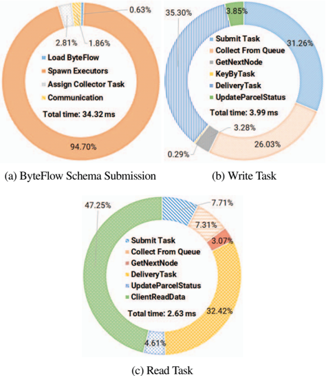 Fig. 5: Visualization of percentage of time spent on each internal component for the core operations of HFlow
In Figure 5, we present the anatomy of operations of HFlow. The three charts represent the ByteFlow Schema Submission and the operation of a Write Schema and a Read Schema. These were achieved via a setup with 40 client processes on a node issuing 512 requests, each of size 512 KB in a file-per-process fashion.
The ByteFlow Submission, in Figure 5a, is dominated by ByteFlow Executor spawning, taking 95% of the time of the whole submission. Task initialization and assigning are both not particularly time consuming, while the relatively low time spent in communication means that the network is not a bottleneck. The anatomy of a Write Schema can be seen in Figure 5b, where HFlow spends a total of 35 . 3%+26 . 03% performing I/O, both collecting Parcels from the application's queue and delivering them to final storage. The anatomy of a Read Schema can be seen in Figure 5c, with most of the time taken up reading data from PFS (47.25%) and submitting the parcels to the client (32.42%). The extra bookkeeping not associated with any of these only takes up about 15% of the total operation time. Note that when executed, all tasks get pipelined. As HFlow is collecting one Data Parcel, another one is being Delivered. Similarly, task submission refers to the initial set-up of the system's task as they get deployed and is thus a one time cost. In all of these graphs, we observe that internal network communication is not a bottleneck for HFlow and that our RPC communication framework is suitable for the system.
- Collector Dynamicity:
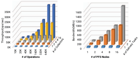 Fig. 6: The performance of dynamically modifying the number of Collector and Delivery Tasks
Collectors are fundamental tasks that are common to every ByteFlow Schema. They are responsible for gathering data from sources, converting them into Data Parcels, and storing them in an in-memory KVS for use by subsequent tasks. The number of Collectors used to service I/O requests for a given application should be dynamic and depend on the rate at which I/O requests are being produced. To demonstrate this, we vary the amount of I/O requests generated by the application and the number of Collectors used to pull those I/O requests.
For this test, we launch an HFlow Manager that has 4 threads and spawns a single HFlow Executor with 16 threads on a different node. We use a ByteFlow Schema with a single Task in the DAG: a Collector. The Collector pulls the data from the client's queue and puts it in the in-memory KVS. We built an application that generates 10K I/O requests per process of size 64KB, and, on one client node, we launch between 1 and 64 processes of this application. The application measures the time at which the first request was produced and the last request was collected, and we calculate throughput in ops/sec. After each test, the KVS is reset to prevent memory from overflowing.
From Figure 6a, we see that when there are 10K requests being produced, only 2 collectors are necessary to get desirable throughput. However, At 320K requests, the 16 collectors case improves throughput by at least 2x when compared to the cases utilizing only 2, 4, or 8 collectors. This shows that the number of Collectors should dynamically change as the behavior of the application changes.
- Delivery Dynamicity: Delivery Tasks are fundamental tasks that are common to every ByteFlow Schema. They are responsible for moving data to the sink. The number of Delivery Tasks for a given application should be dynamic and depend on the rate at which I/O requests are made as well as the nature of the sink, such as the amount of concurrency the sink can support. To demonstrate this, we vary the quantity of I/O requests generated by the application, the number of Delivery Tasks used to move data to storage, and the number of storage nodes in the sink.
For this test, we launch an HFlow Manager that has 4 threads and spawns 16 HFlow Executors among 16 nodes with 16 threads each. The HFlow Executors are divided among the set of nodes. We also create a PFS (the sink) that manages between 1 and 16 HDD-based storage nodes for each test case. We use a ByteFlow Schema that contains a Collector Task and a Delivery Task. We built an application that generates 10K I/O requests per process of size 64KB, and, on a single client node, we launch between 1 and 64 processes of this application. We spawn exactly 4 Collectors and between 1 and 4 Delivery Tasks for each test case. The Delivery Tasks will be mapped to different HFlow Executors so that the PFS can get more concurrency. Since the Collector Tasks are much faster than the Delivery Tasks, we only need 4 Collector Tasks to match the demand of the Delivery Tasks. The application measures the time at which the first request was produced and the time at which the last request was delivered, and we calculate bandwidth from those measurements in MB/sec.
From Figure 6b, we see that when there is 1 PFS node, 1 Delivery Task is sufficient to get desirable bandwidth. However, with 16 PFS nodes, the case with 4 Delivery Tasks improves bandwidth by at least 2x when compared to using only 1 or 2 Delivery Tasks. This is because the PFS with 16 nodes is able to support much higher concurrent access that the higher number of Delivery Tasks can provide. This shows that the number of Delivery Tasks should change depending on the rate at which I/O requests are produced and on the nature of the sink.
- ByteFlow Regulator:
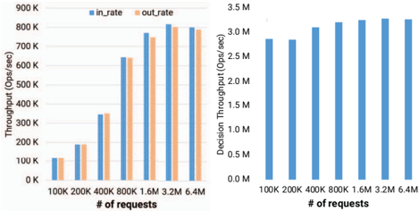 Fig. 7: Visualization of the overall computational and networking costs involving the ByteFlow Regulator
Figure 7 shows the cost of the different activities or operations performed by the ByteFlow Regulator. To perform these tests, we have 40 client processes on one client node and 4 threads on a single ByteFlow Regulator node. The client processes issue I/O requests on a scale between 100k and 6.4 million operations, and we measure inflow and outflow rate in terms of number of operations per second, and the rate of operation decisions.
In Figure 7a, we can see the inflow and outflow operation rates. The inflow and outflow operation rates are fairly similar for a given number of requests. The maximum throughput of about 800000 ops per second is achieved at the 3.2 million request scale. This shows us the network limit of the communication between the two nodes. In Figure 7b, we can see the throughput of decisions made by the ByteFlow Manager. It averages out to about 3.1 million ops per second. There is little variation on this value at scale because the decision algorithm is O(1), depending only on inflow and outflow values which are updated in a decoupled fashion so as to minimize the time spent waiting for their values.
- Cost of Elasticity:
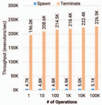 Fig. 8: Throughput of spawn/terminate operations
HFlow has the ability to elastically expand and contract the set of available resources that ByteFlows can use for executing tasks, which is done by either spawning or terminating HFlow Executors. HFlow spawns additional HFlow Executors when the current pool of resources is being over-utilized, and HFlow terminates HFlow Executors when they have no remaining tasks and have been inactive for some period of time. To demonstrate the cost of elasticity, we spawn and terminate a varying number of HFlow Executors among multiple concurrent processes.
For this test, we created an HFlow Manager with 4 threads and access to 16 compute nodes. We built an application that spawns and then immediately terminates an HFlow Executor in a loop, and, on a single client node, we launch exactly 40 processes of this application. We measure the amount of time it takes to complete the spawning and termination tasks individually and report the throughput of the two operations in ops/sec.
In Figure 8, we see that we can spawn between 4,750 and 5,100 HFlow Executors and terminate between 196K and 226K HFlow Executors every second. As expected, spawning HFlow executors is much more expensive than terminating them. This is because spawning has to distribute the binary for the HFlow Executor over an SSH connection, launch it on the compute node, create the thread pool, and establish an RPC connection to the HFlow Manager. Terminate tasks are about 50x faster than spawning. This is because the only cost is a quick RPC call that causes the HFlow Executor process to exit. We also notice that, as the number of operations increases, the throughput increases. This is because the HFlow Manager can accept and service multiple spawn and terminate tasks concurrently due to multi-threading.
C. Application Evaluation
This section is meant to demonstrate the performance of HFlow for managing the IOF, BB, and DS using real-world applications. In each of these tests, we have 32 compute nodes. Each node runs 40 client processes. A PFS that manages 16 storage nodes. And Finally, HFlow running on the storage nodes and composed of a HFlow Regulator with 4 threads, 15 HFlow Executors (8 threads each), and a single ByteFlow Regulator with 4 threads.
- HFlow as an I/O Forwarder:
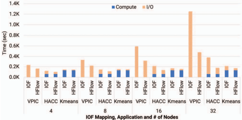 Fig. 9: HFlow as an I/O Forwarder
In order to prevent load imbalance in HFlow, tasks are dynamically mapped to the pool of HFlow Executors during runtime. The goal of this test is to demonstrate the performance impact that the dynamic mapping of IOFs has on real applications as they scale. To do this, we ran three real-world applications that exhibit different I/O behaviors: VPIC, HACC, and Kmeans. VPIC is a particle simulation program that is I/O-intensive; HACCis a simulation program that uses checkpointing and has a balanced workload; and, finally, KMeans is a clustering algorithm that stores most of the data in-memory and is compute-intensive. We compare the performance of these applications when using the typical IOF approach, where batch-based draining and a static mapping from compute node to IOF is used, and with HFlow, where streaming and dynamic mapping is used. We provision 11 compute nodes to VPIC, 11 nodes to HACC, and 10 nodes to KMeans, and the three apps each get 5 HFlow Executors. We assign 1 collector to every node by default, and we vary the number of nodes used by the applications to be between 4 and 32. The nodes are divided as evenly as possible among the applications. Fixed mappings do not change the number of Collectors, whereas dynamic mappings will adapt the number of Collectors based on the workload.
From Figure 9, we see that HFlow performs at least as well as the typical IOFL approach in each of these cases. This is because the I/O demands of the applications are different, requiring different resource mappings. For the 32-node case, we found that 80 collectors were used for VPIC, 32 for HACC, and 16 for KMeans. We also notice that, as the number of processes increases, the performance gained by using HFlow for VPIC and HACC increases. This is because the amount of data being generated increases, resulting in more load imbalance by the static mapping. However, since KMeans is compute-intensive, there was little performance difference between the two approaches. At the largest scale, we see HFlow improves the performance by 3x for VPIC and 2x for HACC compared with the static mapping approach.
- HFlow as a Burst Buffer:
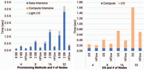 Fig. 10: HFlow as an intermediate I/O resource Manager
In order to prevent load imbalance and over-provisioning in HFlow, InterIORs are provisioned based on the load of the entire system. The goal of this test is to demonstrate the performance impact that the elastic resource provisioning of BBs has on real applications. To do this, we ran an application called Cosmic Tagger, which is a convolutional neural network to separate cosmic pixels, background pixels, and neutrino pixels from an image dataset. It is divided into 3 phases: data-intensive, compute-intensive, and light I/O. We compare provisioning 2 BB nodes, 8 BB nodes, and elastically provisioning between 1 and 15 BB nodes, and we scale the applications to run on 4 to 32 nodes. This will show that, as the scale of the application changes, a fixed allocation of resources will not always be optimal and can lead to load imbalance and over-provisioning.
From Figure 10a, we see that when HFlow runs on 4 nodes, allocating 2 nodes for the application results ˜ 2x less performance since it's not sufficient for the data-intensive phase. Either allocating 8 nodes statically or using elastic provisioning yields the best results. However, 8 BBs results in under-utilization in each of these phases. The elastic approach resulted in no BBs being allocated in the compute phase, 2 BBs in the light I/O phase, and 4 BBs in the data-intensive phase. Furthermore, as the application scales, the performance achieved by HFlow is 3x better than that of the fixed mapping. This is because HFlow was able to adapt to the demands of the different application phases whereas the static mappings became increasingly more imbalanced.
- HFlow as a Data Stager: Data Staging is used for prefetching and caching data. Typically, this requires all of the data to be loaded into the staging area before computations can be performed on it. However, HFlow can be used to perform computations on parts of the data while the rest is being loaded. The goal of this test is to show the performance benefit of using HFlow to asynchronously move data as opposed to the typical DS approach. To do this, we show the performance of KMeans at different scales, which was accomplished via loading an entire dataset into the staging area as opposed to loading 10% of the dataset into the staging area and performing computations while data is asynchronously loaded in. From Figure 10b, we see that when 4 nodes are used to run KMeans, the performances of both approaches are roughly the same. This is because the computation performed on 10% of the dataset is so fast that the data for the next computation is not fully loaded, resulting in data stalls. However, as the scale increases, the performance of HFlow becomes increasingly better, up to 2.5x, than that of the typical approach. The reason for this is that the speed of the compute phase is matched with the inflow of data, removing data stalls and overlapping data movement with computations.
V. RELATED WORK
Stream processing paradigms have been applied to HPC in a few different contexts, but they have not been applied in the context of I/O forwarding technologies. MPI-streams [39] utilizes the streaming paradigm in HPC within the context of adding streaming concepts to the MPI programming model, and pilot-streaming [41] provides a generic abstraction across streaming solutions for HPC. Both of these works accomplish alternative objectives instead of the management of InterIOR, but they provide valuable precedent in the application of streaming paradigms to HPC infrastructure and in the unification of underlying resources.
Integration of the different hardware in the storage hierarchy has been proposed in works such as Hermes [46] and Cambridge Data Accelerator [47]; however, these technologies have the objective of providing multi-level file buffering rather than multi-level I/O forwarding, and therefore fail to provide the generic source and sink abstractions, which are a prerequisite to multi-layer I/O forwarding. This means that, while they unify access to multi-layer HPC hardware, they make assumptions about the available hardware and software architecture which will limit them to particular behaviors across particular types of sources or sinks (such as applications and files). For example, none of these systems can interface with other software systems; they require direct control of the hardware resources in order to manage them. This is a major restriction to the applicability and flexibility of these systems.
Dynamic and elastic provisioning of I/O forwarding resources has been proposed in Ji et al [19] and Harmonia [12], but they limit their data sinks to a singular type of InterIOR (I/O Forwarders or Burst Buffers) and make assumptions about the nature of their sources (typically assuming that the source is an application), whereas HFlow allows more generic source and sink definitions, permitting a full scope of resource allocation in a fashion that is interoperable with other storage technologies. Furthermore, the general idea of dynamic scheduling has been explored in the context of I/O scheduling by CALCioM [48] and Gainaru et al [49]; none of these works explore run-time dynamic resource scheduling in the context of InterIOR as a whole.
VI. CONCLUSIONS AND FUTURE WORK
Alleviating the I/O bottleneck has become a significant concern for the scientific community. Proposed solutions involved the introduction of intermediate layers of storage resources. Yet, this intermediate I/O resources suffer issues rooted in the independent development of software abstractions and their inherent rigidity. In this work, we have proposed HFlow , a new approach to data forwarding system that utilizes a real-time data movement paradigm. HFlow introduces a unified data movement abstraction (the ByteFlow ) that allows global management of intermediate I/O resources while providing data-independent tasks that enable dynamic resource provisioning. Moreover, the processing elements executing the ByteFlows are designed to be ephemeral and, hence, enable elastic management of intermediate storage resources. Finally, HFlow empowers users to define in-transit computations over data. Our results show that applications running under HFlow display an increase in performance of 3x when compared with alternative solutions for managing intermediate I/O resources.
As future work, we want to explore enhancements to our ByteFlow Schema in order to determine methods to make it more diverse; we are especially interested in exploring the possible interactions of HFlow with time-based storage systems such as log stores or time-series databases.
ACKNOWLEDGMENT
This work is supported by National Science Foundation under OCI-1835764 and CSR-1814872.
REFERENCES
[1] R. T. Kouzes, G. A. Anderson, S. T. Elbert, I. Gorton, and D. K. Gracio, 'The changing paradigm of data-intensive computing,' Computer , vol. 42, no. 1, pp. 26-34, 2009.
[2] D. Zhao, Z. Zhang, X. Zhou, T. Li, K. Wang, D. Kimpe, P . Carns, R. Ross, and I. Raicu, 'Fusionfs: Toward supporting data-intensive scientific applications on extreme-scale high-performance computing systems,' in 2014 IEEE International Conference on Big Data (Big Data) , 2014, pp. 61-70.
[3] Z. Liu, R. Lewis, R. Kettimuthu, K. Harms, P. Carns, N. Rao, I. Foster, and M. E. Papka, 'Characterization and identification of hpc applications at leadership computing facility,' in Proceedings of the 34th ACM International Conference on Supercomputing , ser. ICS '20. New York, NY, USA: Association for Computing Machinery, 2020. [Online]. Available: https://doi.org/10.1145/3392717.3392774
[4] Y. Kim, R. Gunasekaran, G. M. Shipman, D. A. Dillow, Zhe Zhang, and B. W. Settlemyer, 'Workload characterization of a leadership class storage cluster,' in 2010 5th Petascale Data Storage Workshop (PDSW '10) , 2010, pp. 1-5.
[5] J. He, J. Bent, A. Torres, G. Grider, G. Gibson, C. Maltzahn, and X.-H. Sun, 'I/o acceleration with pattern detection,' in Proceedings of the 22nd International Symposium on High-Performance Parallel and Distributed Computing , ser. HPDC '13. New York, NY, USA: Association for Computing Machinery, 2013, p. 25-36. [Online]. Available: https://doi.org/10.1145/2462902.2462909
[6] J. Lofstead, I. Jimenez, C. Maltzahn, Q. Koziol, J. Bent, and E. Barton, 'Daos and friends: A proposal for an exascale storage system,' in SC '16: Proceedings of the International Conference for High Performance Computing, Networking, Storage and Analysis , 2016, pp. 585-596.
[7] N. Liu, J. Cope, P . Carns, C. Carothers, R. Ross, G. Grider, A. Crume, and C. Maltzahn, 'On the role of burst buffers in leadership-class storage systems,' in 2012 IEEE 28th Symposium on Mass Storage Systems and Technologies (MSST) , 2012, pp. 1-11.
[8] N. Ali, P . Carns, K. Iskra, D. Kimpe, S. Lang, R. Latham, R. Ross, L. Ward, and P. Sadayappan, 'Scalable i/o forwarding framework for high-performance computing systems,' in 2009 IEEE International Conference on Cluster Computing and Workshops , 2009, pp. 1-10.
[9] K. Tang, P. Huang, X. He, T. Lu, S. S. V azhkudai, and D. Tiwari, 'Toward managing hpc burst buffers effectively: Draining strategy to regulate bursty i/o behavior,' in 2017 IEEE 25th International Symposium on Modeling, Analysis, and Simulation of Computer and Telecommunication Systems (MASCOTS) . IEEE, 2017, pp. 87-98.
[10] H. Abbasi, M. Wolf, G. Eisenhauer, S. Klasky, K. Schwan, and F. Zheng, 'DataStager: scalable data staging services for petascale applications,' vol. 13, pp. 277-290, 2010.
[11] K. Ohta, D. Kimpe, J. Cope, K. Iskra, R. Ross, and Y . Ishikawa, 'Optimization techniques at the i/o forwarding layer,' in 2010 IEEE International Conference on Cluster Computing . IEEE, 2010, pp. 312-321.
[12] A. Kougkas, H. Devarajan, X. H. Sun, and J. Lofstead, 'Harmonia: An Interference-Aware Dynamic I/O Scheduler for Shared Non-volatile Burst Buffers,' in Proceedings -IEEE International Conference on Cluster Computing, ICCC , vol. 2018-September. Institute of Electrical and Electronics Engineers Inc., oct 2018, pp. 290-301.
[13] H. Sung, J. Bang, C. Kim, H.-S. Kim, A. Sim, G. K. Lockwood, and H. Eom, 'Bbos: Efficient hpc storage management via burst buffer over-subscription,' in 2020 20th IEEE/ACM International Symposium on Cluster, Cloud and Internet Computing (CCGRID) . IEEE, 2020, pp. 142-151.
[14] C. Docan, M. Parashar, and S. Klasky, 'Dataspaces: an interaction and coordination framework for coupled simulation workflows,' Cluster Computing , vol. 15, no. 2, pp. 163-181, 2012.
[15] H. Khetawat, C. Zimmer, F. Mueller, S. Atchley, S. S. Vazhkudai, and M. Mubarak, 'Evaluating burst buffer placement in hpc systems,' in 2019 IEEE International Conference on Cluster Computing (CLUSTER) . IEEE, 2019, pp. 1-11.
[16] B. Yang, X. Ji, X. Ma, X. Wang, T. Zhang, X. Zhu, N. El-Sayed, H. Lan, Y. Yang, J. Zhai, W. Liu, and W. Xue, 'End-to-end i/o monitoring on a leading supercomputer,' in 16th USENIX Symposium on Networked Systems Design and Implementation (NSDI 19) . Boston, MA: USENIX Association, Feb. 2019, pp. 379-394. [Online]. Available: https://www.usenix.org/conference/nsdi19/presentation/yang
[17] F. Zahid, E. G. Gran, B. Bogda´ nski, B. D. Johnsen, and T. Skeie, 'Efficient network isolation and load balancing in multi-tenant hpc clusters,' Future Generation Computer Systems , vol. 72, pp. 145 - 162, 2017. [Online]. Available: http://www.sciencedirect.com/science/article/pii/S0167739X16300735
[18] G. K. Lockwood, D. Hazen, Q. Koziol, R. S. Canon, K. Antypas, J. Balewski, N. Balthaser, W. Bhimji, J. Botts, J. Broughton, T. L. Butler, G. F. Butler, R. Cheema, C. Daley, T. Declerck, L. Gerhardt, W. E. Hurlbert, K. A. Kallback-Rose, S. Leak, J. Lee, R. Lee, J. Liu, K. Lozinskiy, D. Paul, N. Prabhat, C. Snavely, J. Srinivasan, T. Stone Gibbins, and N. J. Wright, 'Storage 2020: A vision for the future of hpc storage,' 10 2017. [Online]. Available: https://www.osti.gov/biblio/1632124
[19] X. Ji, in Wuxi, B. Yang, T. Zhang, X. Ma, X. Zhu, X. Wang, N. El-Sayed, J. Zhai, W. Liu, and W. Xue, Automatic, ApplicationAware I/O Forwarding Resource Allocation . [Online]. Available: https://www.usenix.org/conference/fast19/presentation/ji
[20] Institute of Electrical and Electronics Engineers, On the Load Imbalance Problem of I/O Forwarding Layer in HPC Systems .
[21] J. Yu, W. Yang, F. Wang, D. Dong, J. Feng, and Y . Li, 'Spatially Bursty I/O on Supercomputers: Causes, Impacts and Solutions,' IEEE Transactions on Parallel and Distributed Systems , vol. 31, no. 12, pp. 2908-2922, dec 2020. [Online]. Available: https://ieeexplore.ieee.org/document/9127806/
[22] A. Souza, M. Rezaei, E. Laure, and J. Tordsson, 'Hybrid resource management for hpc and data intensive workloads,' in 2019 19th IEEE/ACM International Symposium on Cluster, Cloud and Grid Computing (CCGRID) , 2019, pp. 399-409.
[23] O. Yildiz, M. Dorier, S. Ibrahim, R. Ross, and G. Antoniu, 'On the Root Causes of Cross-Application I/O Interference in HPC Storage Systems,' in Proceedings - 2016 IEEE 30th International Parallel and Distributed Processing Symposium, IPDPS 2016 . Institute of Electrical and Electronics Engineers Inc., jul 2016, pp. 750-759.
[24] M. Parashar, 'Addressing the petascale data challenge using in-situ analytics,' in Proceedings of the 2nd International Workshop on Petascal Data Analytics: Challenges and Opportunities , ser. PDAC '11. New York, NY, USA: Association for Computing Machinery, 2011, p. 35-36. [Online]. Available: https://doi.org/10.1145/2110205.2110212
[25] P. C. Wong, H. Shen, C. R. Johnson, C. Chen, and R. B. Ross, 'The top 10 challenges in extreme-scale visual analytics,' IEEE Computer Graphics and Applications , vol. 32, no. 4, pp. 63-67, 2012.
[26] J. C. Bennett, H. Abbasi, P . Bremer, R. Grout, A. Gyulassy, T. Jin, S. Klasky, H. Kolla, M. Parashar, V . Pascucci, P . Pebay, D. Thompson, H. Y u, F. Zhang, and J. Chen, 'Combining in-situ and in-transit processing to enable extreme-scale scientific analysis,' in SC '12: Proceedings of the International Conference on High Performance Computing, Networking, Storage and Analysis , 2012, pp. 1-9.
[27] S. Duan, P. Subedi, K. Teranishi, P. Davis, H. Kolla, M. Gamell, and M. Parashar, 'Scalable data resilience for in-memory data staging,' in 2018 IEEE International Parallel and Distributed Processing Symposium (IPDPS) . IEEE, 2018, pp. 105-115.
[28] N. S. C. in Guangzhou, 'Tianhe-2a supercomputer,' 2018. [Online]. Available: https://www.top500.org/system/177999/
[29] J. C. for Advanced HPC, 'Oakforest-pacs supercomputer,' 2016. [Online]. Available: https://www.top500.org/system/178932/
[30] J. Dongarra and P . Luszczek, 'Top500,' in Encyclopedia of Parallel Computing , 2011, pp. 2055-2057.
[31] H. Devarajan, A. Kougkas, and X.-H. Sun, 'Hfetch: Hierarchical data prefetching for scientific workflows in multi-tiered storage environments,' in 2020 IEEE International Parallel and Distributed Processing Symposium (IPDPS) . IEEE, 2020, pp. 62-72.
[32] M. Romanus, R. B. Ross, and M. Parashar, 'Challenges and Considerations for Utilizing Burst Buffers in High-Performance Computing,' Tech. Rep., 2018.
[33] N. E. R. S. C. Center, 'Nersc's cori supercomputer,' 2020. [Online]. Available: https://www.nersc.gov/systems/cori/
[34] L. A. N. Laboratory, 'Trinity: Advanced technology system,' 2020. [Online]. Available: https://www.lanl.gov/projects/trinity/
[35] K. Jacobs and K. Surdy, 'Apache flink: Distributed stream data processing,' Tech. Rep., 2016.
[36] A. Flink, 'Apache flink,stateful computations over data streams,' 2020. [Online]. Available: https://flink.apache.org/
[37] T. Akidau, R. Bradshaw, C. Chambers, S. Chernyak, R. J. Fern´ andez, F. Fern´ andez-Moctezuma, R. Lax, S. Mcveety, D. Mills, F. Perry, E. Schmidt, and S. Whittle Google, 'The Dataflow Model: A Practical Approach to Balancing Correctness, Latency, and Cost in Massive-Scale, Unbounded, Out-of-Order Data Processing,' Tech. Rep., 2150.
[38] A. Kafka, 'Apache kafka, a distributed streaming platform,' 2020. [Online]. Available: https://kafka.apache.org/
[39] E. P. Mancini, G. Marsh, and D. K. Panda, 'An MPI-Stream Hybrid Programming Model for Computational Clusters,' Tech. Rep.
[40] I. B. Peng, S. Markidis, E. Laure, D. Holmes, and M. Bull, 'A data streaming model in mpi,' in Proceedings of the 3rd Workshop on Exascale MPI , 2015, pp. 1-10.
[41] A. Luckow, G. Chantzialexiou, and S. Jha, 'Pilot-Streaming: A Stream Processing Framework for High-Performance Computing,' jan 2018. [Online]. Available: http://arxiv.org/abs/1801.08648
[42] T. R. of the University of California, 'Ior: Hpc io benchmark,' 2003. [Online]. Available: https://github.com/hpc/ior.git
[43] G. K. Lockwood, D. Hazen, Q. Koziol, R. Canon, K. Antypas, J. Balewski, N. Balthaser, W. Bhimji, J. Botts, J. Broughton et al. , 'Storage 2020: A vision for the future of hpc storage,' 2017.
[44] IIT, 'Ares cluster,' http://www.cs.iit.edu/ \ ∼ scs/resources.html \ #content6-8p, 2019, accessed: 2019-04-24.
[45] H. Devarajan, A. Kougkas, K. Bateman, and X. H. Sun, 'Hcl: Distributing parallel data structures in extreme scales,' in 2020 IEEE International Conference on Cluster Computing (CLUSTER) , 2020, pp. 248-258.
[46] A. Kougkas, H. Devarajan, and X.-H. Sun, 'Hermes: A Heterogeneous-Aware Multi-Tiered Distributed I/O Buuering System,' 2018.
[47] A. King, 'Cambridge Data Accelerator,' Tech. Rep. [Online]. Available: https://glennklockwood.blogspot.com/2017/03/,
[48] M. Dorier, G. Antoniu, R. Ross, D. Kimpe, and S. Ibrahim, 'CALCioM: Mitigating I/O interference in HPC systems through cross-application coordination,' in Proceedings of the International Parallel and Distributed Processing Symposium, IPDPS . IEEE Computer Society, 2014, pp. 155-164.
[49] A. Gainaru, G. Aupy, A. Benoit, F. Cappello, Y . Robert, and M. Snir, 'Scheduling the i/o of hpc applications under congestion,' in 2015 IEEE International Parallel and Distributed Processing Symposium . IEEE, 2015, pp. 1013-1022.